US449870A - Snap-hook - Google Patents
Snap-hook Download PDFInfo
- Publication number
- US449870A US449870A US449870DA US449870A US 449870 A US449870 A US 449870A US 449870D A US449870D A US 449870DA US 449870 A US449870 A US 449870A
- Authority
- US
- United States
- Prior art keywords
- hook
- snap
- bolt
- spring
- body portion
- Prior art date
- Legal status (The legal status is an assumption and is not a legal conclusion. Google has not performed a legal analysis and makes no representation as to the accuracy of the status listed.)
- Expired - Lifetime
Links
- 238000010276 construction Methods 0.000 description 1
- 238000009877 rendering Methods 0.000 description 1
Images
Classifications
-
- F—MECHANICAL ENGINEERING; LIGHTING; HEATING; WEAPONS; BLASTING
- F16—ENGINEERING ELEMENTS AND UNITS; GENERAL MEASURES FOR PRODUCING AND MAINTAINING EFFECTIVE FUNCTIONING OF MACHINES OR INSTALLATIONS; THERMAL INSULATION IN GENERAL
- F16B—DEVICES FOR FASTENING OR SECURING CONSTRUCTIONAL ELEMENTS OR MACHINE PARTS TOGETHER, e.g. NAILS, BOLTS, CIRCLIPS, CLAMPS, CLIPS OR WEDGES; JOINTS OR JOINTING
- F16B45/00—Hooks; Eyes
- F16B45/02—Hooks with pivoting or elastically bending closing member
- F16B45/036—Hooks with pivoting or elastically bending closing member with an elastically bending closing member
-
- A—HUMAN NECESSITIES
- A44—HABERDASHERY; JEWELLERY
- A44C—PERSONAL ADORNMENTS, e.g. JEWELLERY; COINS
- A44C5/00—Bracelets; Wrist-watch straps; Fastenings for bracelets or wrist-watch straps
- A44C5/14—Bracelets; Wrist-watch straps; Fastenings for bracelets or wrist-watch straps characterised by the way of fastening to a wrist-watch or the like
- A44C5/145—Hooks
Definitions
- This invention relates to certain new and useful improvements in snap-hooks for harnesses; and it has for its obj eet, among others, to provide a simple, cheap, and durable device of this character.
- A designates the body portion of the snap-hook, formed with cars a, throughwhich is passed the bolt or rod B to receive the end of the trace in the usual manner.
- 0 is a spring-bolt arranged to connect with the whiffletree.
- the snap-hook is arranged to open and close by means of said springbolt, which is formed of a body portion to complete the contour of the hook of the snaphook, as shown in Figs. 1 and 2, having its outer end beveled or formed on an incline, as shown in Fig. 1, to conform to the tapered end of the hook portion of the snap-hook.
- the belt is formed with a reduced springshank c, which is tapered to a point and is forced into a socket c in the body of the snaphook, as seen best in Fig. 1, said socket at its outer end being enlarged into the space in- ,closed by the ring portion of the snap-hook,
- the spring portion 0 of the bolt extends from one side of the circular portion thereof,'leaving a square shoulder e, which bears against the end of the body portion in which the socket is formed, as shown in Fig. 1, so as to relieve the spring portion of the spring in case pressure is broughtto bear against the body portion of the bolt, which completes the contour of the ring or hook portion of the snap-hook.
- the body portion of the bolt will give or yield sufficient to allow of the passage of the whiffletree-ring, as indicated by dotted lines in Fig. 1, but automatically return to its normal position after the ring has passed. It forms a safety snap hook, as the whiffietreering cannot accidentally become detached either while going downhill or on the slackingof the traces.
- the bevel of the outer end of the body portion of the bolt, together with the outer shoulder 6, serves to prevent breakage of the bolt by sudden strain thereon.
- the body portion of the bolt is provided with a thumb-piece or projection f, which is located upon the inner side of the spring-bolt, thus rendering it much less liable to come in contact with any obstructions which might disconnect the spring-bolt.
- the device is simple, inexpensive, and in practice has proved most eflieient.
- thebolt O and its tongue be formed of a single piece of material, as it is more durable, cheaper, and less liable to get out of order. It is also deemed important that the said tongue be tapered and springs and forced into a socket in the body portion of the snap-hook and there held by frictional contact of the parts, thus avoiding the necessity of the employment of screws or other fastening means, as has heretofore been proposed.
- tapered spring portion a beveled outer MILTON R. MAXSON, end, square shoulder c at the junction of the JOHN WV. STRATER.
Landscapes
- Engineering & Computer Science (AREA)
- General Engineering & Computer Science (AREA)
- Mechanical Engineering (AREA)
- Hooks, Suction Cups, And Attachment By Adhesive Means (AREA)
Description
(No Model.) I J. L. BUCKINGHAM & J. P. YEATES.
SNAP HOOK. No. 449,870. PatefitedApL- '7, 1891.
' lllllllll-lmllllllllllllllllllll IIWIIIIIlllullllllllllllllllllll wi byuzaogo, Z Z- BW a7 UNITED STATES PATENT OFFICE.
JOHN L. BUOKINGHAM AND JOHN F. YEATES, OF HERMOSA, SOUTH DAKOTA.
SNAP-HOOK.
SPECIFICATION forming part of Letters Patent No. 449,870, dated'April *7, 1891. Application filed septemhcr 15, 1890- Serial No. 3651068 (N0 mvdeL) To all whom it may concern.-
Beit known that we, JOHN L. BUCKINGHAM and JOHN F. YEATES, citizens of the United States, residing at Hermosa, in the county of Custer, State of South Dakota, have invented certain new and useful Improvements in Snap- IIooks, of which the following is a specification, reference being had therein to the accompanying drawings.
This invention relates to certain new and useful improvements in snap-hooks for harnesses; and it has for its obj eet, among others, to provide a simple, cheap, and durable device of this character.
The novelty resides in the peculiarities of construction of the snap-hook, as more fully hereinafter described, shown in the drawings, and then particularly pointed out in the appended claim.
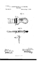
The invention is clearly illustrated in the accompanying drawings, which, with the letters of reference marked thereon,form a part of this specification, and in which- Figure 1 is a side View of the snap-hook with portions broken away. Fig. 2 is an edge view of Fig. 1. Fig. 3 is a perspective view of the spring-bolt detached.
Like letters of reference indicate like parts throughout the several views.
Referring now to the details of the drawings by letter, A designates the body portion of the snap-hook, formed with cars a, throughwhich is passed the bolt or rod B to receive the end of the trace in the usual manner.
0 is a spring-bolt arranged to connect with the whiffletree. The snap-hook is arranged to open and close by means of said springbolt, which is formed of a body portion to complete the contour of the hook of the snaphook, as shown in Figs. 1 and 2, having its outer end beveled or formed on an incline, as shown in Fig. 1, to conform to the tapered end of the hook portion of the snap-hook. The belt is formed with a reduced springshank c, which is tapered to a point and is forced into a socket c in the body of the snaphook, as seen best in Fig. 1, said socket at its outer end being enlarged into the space in- ,closed by the ring portion of the snap-hook,
as seen best in Fig. 1, so as to allow free movement of the spring-bolt, as indicated by dot-- ted lines in Fig. l. The spring portion 0 of the bolt extends from one side of the circular portion thereof,'leaving a square shoulder e, which bears against the end of the body portion in which the socket is formed, as shown in Fig. 1, so as to relieve the spring portion of the spring in case pressure is broughtto bear against the body portion of the bolt, which completes the contour of the ring or hook portion of the snap-hook.
In practice the body portion of the bolt will give or yield sufficient to allow of the passage of the whiffletree-ring, as indicated by dotted lines in Fig. 1, but automatically return to its normal position after the ring has passed. It forms a safety snap hook, as the whiffietreering cannot accidentally become detached either while going downhill or on the slackingof the traces. The bevel of the outer end of the body portion of the bolt, together with the outer shoulder 6, serves to prevent breakage of the bolt by sudden strain thereon.
The body portion of the bolt is provided with a thumb-piece or projection f, which is located upon the inner side of the spring-bolt, thus rendering it much less liable to come in contact with any obstructions which might disconnect the spring-bolt.
The device is simple, inexpensive, and in practice has proved most eflieient.
It is deemed important that thebolt O and its tongue be formed of a single piece of material, as it is more durable, cheaper, and less liable to get out of order. It is also deemed important that the said tongue be tapered and springs and forced into a socket in the body portion of the snap-hook and there held by frictional contact of the parts, thus avoiding the necessity of the employment of screws or other fastening means, as has heretofore been proposed.
What we claim as new is In testimony whereof we affix our signatures The snap-hook described, consisting of a in presence of two witnesses;
body portion formed with the recess extend- T in g into the body of the body portion and havgggggg 5 i ngenlarged entrance, and the spring-bolt completing the contour of the eye and formed with Witnesses to signature of Buckingham:
the tapered spring portion a, beveled outer MILTON R. MAXSON, end, square shoulder c at the junction of the JOHN WV. STRATER.
bodyportion and spring portion, and a thumb- Witnesses to signature of Yeatesz. 10 piece upon the inner side of the body portion A. ARNOLD,
of the bolt, substantially as described. GALLAND.
Publications (1)
| Publication Number | Publication Date |
|---|---|
| US449870A true US449870A (en) | 1891-04-07 |
Family
ID=2518753
Family Applications (1)
| Application Number | Title | Priority Date | Filing Date |
|---|---|---|---|
| US449870D Expired - Lifetime US449870A (en) | Snap-hook |
Country Status (1)
| Country | Link |
|---|---|
| US (1) | US449870A (en) |
Cited By (2)
| Publication number | Priority date | Publication date | Assignee | Title |
|---|---|---|---|---|
| US6244803B1 (en) * | 1999-02-05 | 2001-06-12 | Smr Technologies, Inc. | Aircraft cargo barrier net |
| US20050142033A1 (en) * | 2003-11-04 | 2005-06-30 | Meso Scale Technologies, Llc. | Modular assay plates, reader systems and methods for test measurements |
-
0
- US US449870D patent/US449870A/en not_active Expired - Lifetime
Cited By (2)
| Publication number | Priority date | Publication date | Assignee | Title |
|---|---|---|---|---|
| US6244803B1 (en) * | 1999-02-05 | 2001-06-12 | Smr Technologies, Inc. | Aircraft cargo barrier net |
| US20050142033A1 (en) * | 2003-11-04 | 2005-06-30 | Meso Scale Technologies, Llc. | Modular assay plates, reader systems and methods for test measurements |
Similar Documents
| Publication | Publication Date | Title |
|---|---|---|
| US449870A (en) | Snap-hook | |
| US132247A (en) | Improvement in snap-hooks | |
| US456137A (en) | Snap-hook | |
| US652996A (en) | Snap-hook. | |
| US453877A (en) | Clarence p | |
| US315796A (en) | James b | |
| US568617A (en) | Hame-fastener | |
| US160266A (en) | Improvement in harness-snaps | |
| US499304A (en) | Snap-hook | |
| US1212765A (en) | Harness attachment. | |
| US1214717A (en) | Safety-hook. | |
| US454034A (en) | Wells r | |
| US306917A (en) | Island | |
| US81026A (en) | William b | |
| US286530A (en) | Snap-hook | |
| US172355A (en) | Improvement in snap-hooks | |
| US243031A (en) | Thill-coupling | |
| US458761A (en) | Tug-hook | |
| US153823A (en) | Improvement in bracelets | |
| US465530A (en) | Remembrance lindsay kirby | |
| US120386A (en) | Improvement in snap-hooks | |
| US240123A (en) | Joseph t | |
| US274694A (en) | Territory | |
| US831991A (en) | Hook. | |
| US739226A (en) | Safety snap-hook. |
